
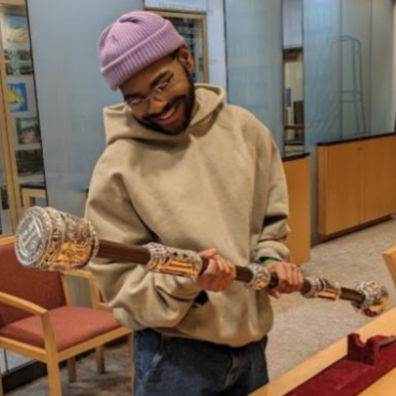
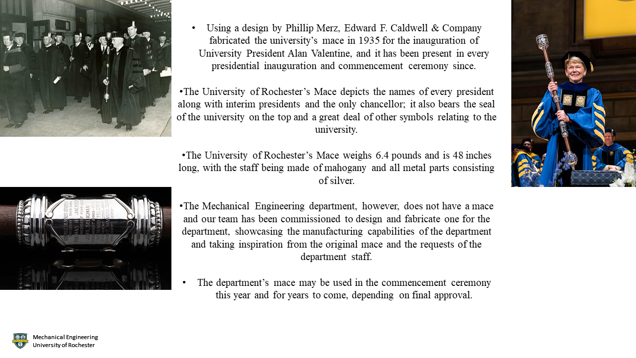
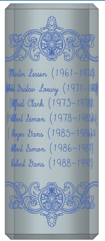
The story of the University of Rochester's ceremonial mace(pictured above) began in 1935 when it was designed by Phillip Merz(who also designed a significant portion of the River Campus) and manufactured by the now defunct Edward F. Caldwell and Company for the inauguration of University President Alan Valentine. The mace was constructed out of a mahogany staff along with a head, base, bands of silver, and an escutcheon. From end to end it is 48 inches long, and surprisingly weighs only 6.4 lbs as most of the mace is hollow, held together by a thin silver rod through its center. At the time the escutcheon beared the names and years served of every University president and interim president until that point, along with the name of the only chancellor in the University's history. The mace then became a required piece of every inauguration and commencement ceremony at the University, and has the name and inauguration year of every entering president and interim president engraved for their inauguration, along with their final year for their departure. In the decades since it was manufactured, an additional escutcheon was added to the mace due to the need for more engraving space. The mace also depicts many symbols of the University including the University's seal and several dandelions.
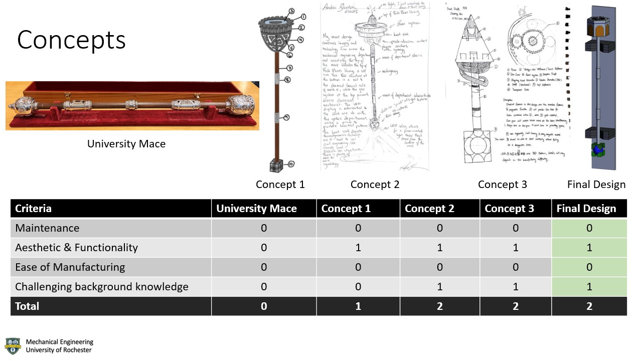
For our Spring 2023 Senior Design Day project, we were tasked with designing and manufacturing a mace for the Department of Mechanical Engineering that depicts symbology of the work and history of the Department, along with showcasing both a wide variety of materials and the manufacturing capabilities of the University. If approved, this mace will be used at the Department's annual commencement ceremony for the foreseeable future. We began this process by researching the history of the University's mace, which led us to discover from an old Facebook post that the mace was kept at the University Archives, and that the relevant contact for this was the University Archivist, Mellisa Mead. After greatly confusing the receptionist, to our surprise and delight, Melissa Mead was able to schedule us two separate appointments to view and document the University's Mace(picture below). During these visits we took several measurements and each member of the team was allowed to briefly hold the mace. As the original mace is 48 inches long, we decided that the Department's should not be longer than 48 inches to not give the appearance of attempting to overshadow the original.
We continued our research process by interviewing many of the members of the Department about their thoughts on the mace, and presenting them with the flyer below detailing the project.
Taking inspiration from the original mace, the thoughts of the Department, and also incorporating their own ideas, each member of our team developed at least one preliminary design, and they are pictured below. The concepts from these designs were then evaluated by the team and the sponsor as to if they could or should be included in the final design.
From here we agreed upon a general design consisting of a structure of arches containing slots for icon plates and a gear system for the top, a BCC structure for the bottom, and a mahogany staff(below).
An alternative version of this design was developed involving the icon plates being backlit by relatively powerful LEDs(below), however this design was discarded due to time constraints, weight, and the need for regular battery replacements.
Our final design takes the general design above and heavily modifies it for manufacturability, and implements symbology on the icon plates, clasps, and the arches(all shown below).
Below this point is our final report, which uses a writing style specified by the Department and is very technical in nature. All figures, tables, and equations that are mentioned below are included in the appendix at the bottom of the page.
For this project, the team was tasked with designing and manufacturing a ceremonial mace to be used by the Department of Mechanical Engineering at the University of Rochester. This process began by researching the history of the University’s mace as well as a general understanding of maces, including two visits to view and document the original mace. The team continued the research by inquiring about the thoughts and requests of the Department staff, and then heavily considered this information for the preliminary designs. After much deliberation, the team decided on a design consisting of a BCC structure for the base, a carbon fiber tube enclosing a carbon steel rod for the staff, two handles bearing the names of all past and present chairs of the Department, and a structure consisting of arches, a gear system, and wooden plates bearing symbology of the field and the work of the Department. A stand consisting of red oak wood and felt was also designed to support the mace and protect it from damage when it is not in use. As this project also serves to display the University’s manufacturing capabilities, this device was fabricated using a wide range of techniques including machining by hand, 4-Axis CNC, laser cutting, anodization, and 3D printing. If the final product is approved, the mace will be used in the Department’s commencement ceremony this year and every year.
Every year, the Department holds its own commencement ceremony separate from the University’s main ceremony. For the main ceremony, it is a yearly tradition that the University’s mace be displayed prominently during several parts of the ceremony. The Department, however, does not have its own mace and some members within the Department have raised the idea. The Department has instructed us to manufacture a mace that depicts many of the aspects of the field and the work done by the Department. To best represent the current abilities of the department, a wide range of in-house manufacturing capabilities are to be used. If approved, this mace would be used at the Department’s commencement ceremony this year 2023 and for many years to come.
The main deliverable for this project is to produce a ceremonial mace for the Department, along with a technical report and documentation of iconography. Both documents are essential to give insights into the mace's design process. The last deliverable was to create a stand to display the mace when not in use, and to minimize the risk of damage during storage.
The requirements for this project were organized to cover all aspects of mechanical design at the University of Rochester. The first requirement was that the mace be made of the widest variety of materials available. The use of multiple materials helps express the capabilities an engineer has to not be limited by resources. Since the mace is strictly for the Mechanical Engineering Department, the next requirement is that the mace must include at least one symbol from each of the six branches of mechanical engineering. The next requirement is that the mace be manufactured from the widest variety of available manufacturing techniques possible at the University, both to demonstrate the manufacturing methods that are taught to students and to demonstrate the capabilities of the University. The final requirement is that the mace will be highly ornamental as the mace must be visually aesthetic when being displayed during the Department’s commencement ceremony.
Specifications for this project were placed to help define a successful presentation of the mace. The first specification is that mace will weigh no more than 25 lbf. This specification aims to prevent a physical burden on the person designated to carry the mace at the commencement ceremony. The next specification is that the mace will be no longer than 48 inches in length. This is to prevent the mace from being longer than the length of the University’s mace and is also crucial to the visibility of the audience. The last specification was that the largest radius will not exceed 12 inches. This specification was to help ensure the design's ornamental look as well as for balancing the mace itself.
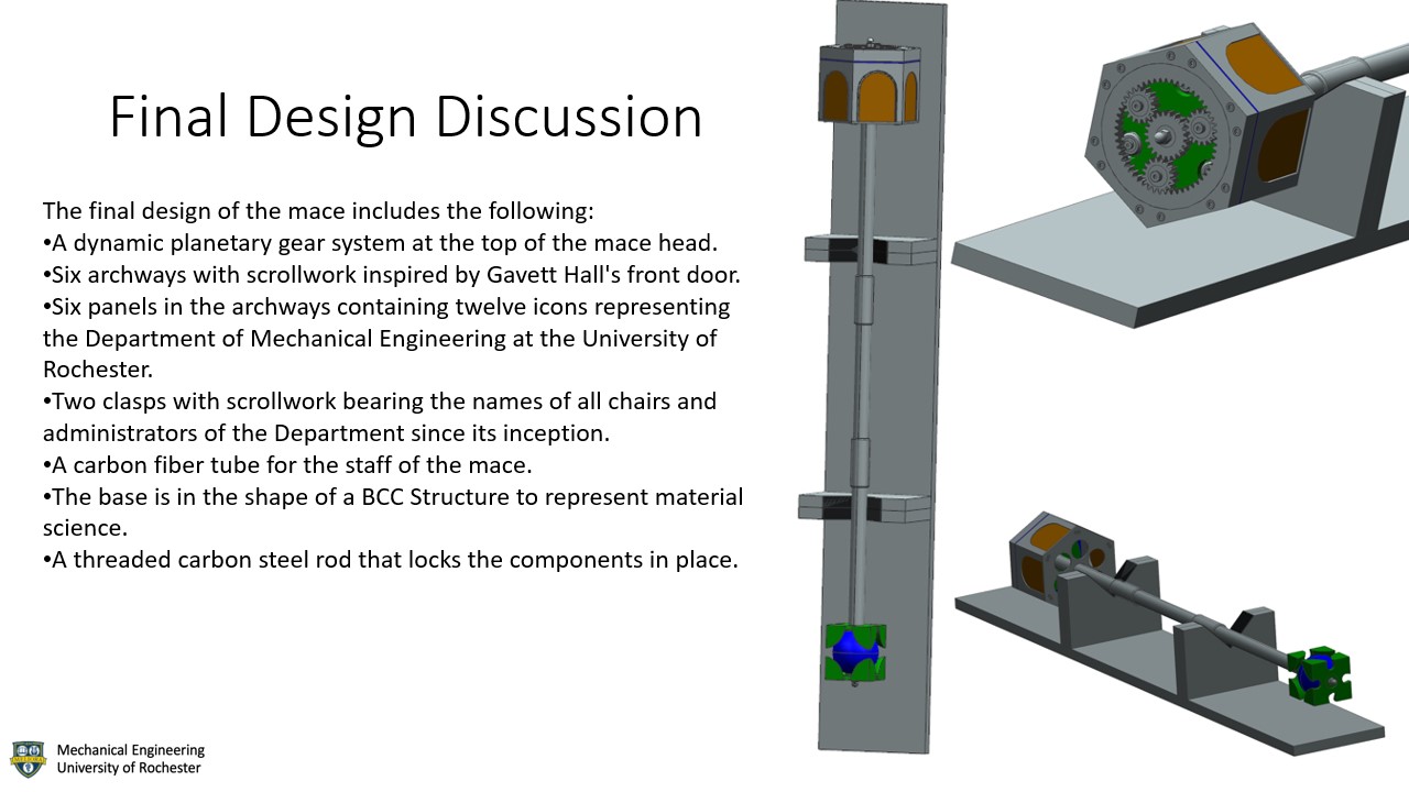
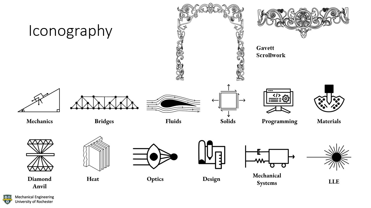
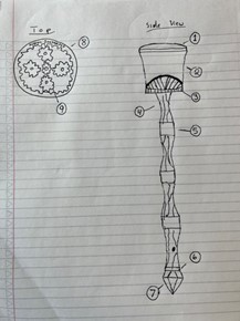
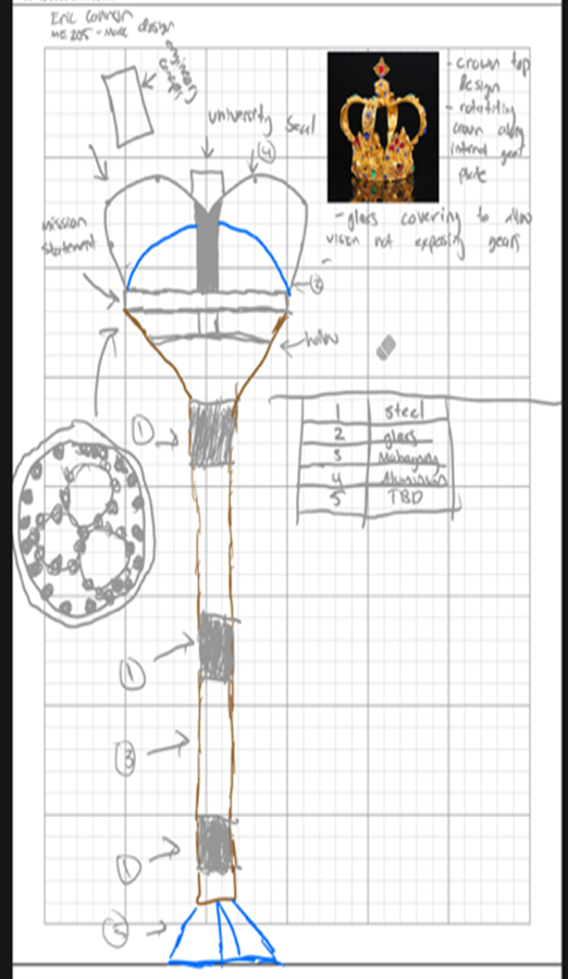
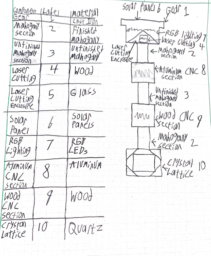
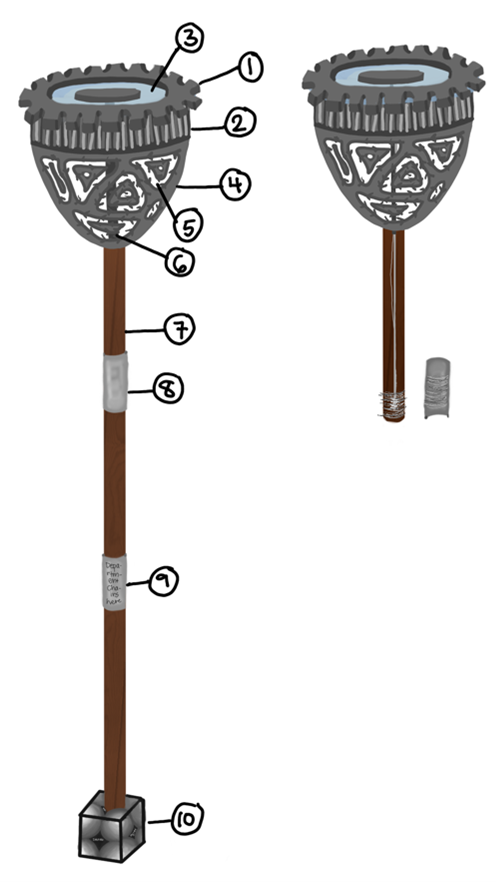
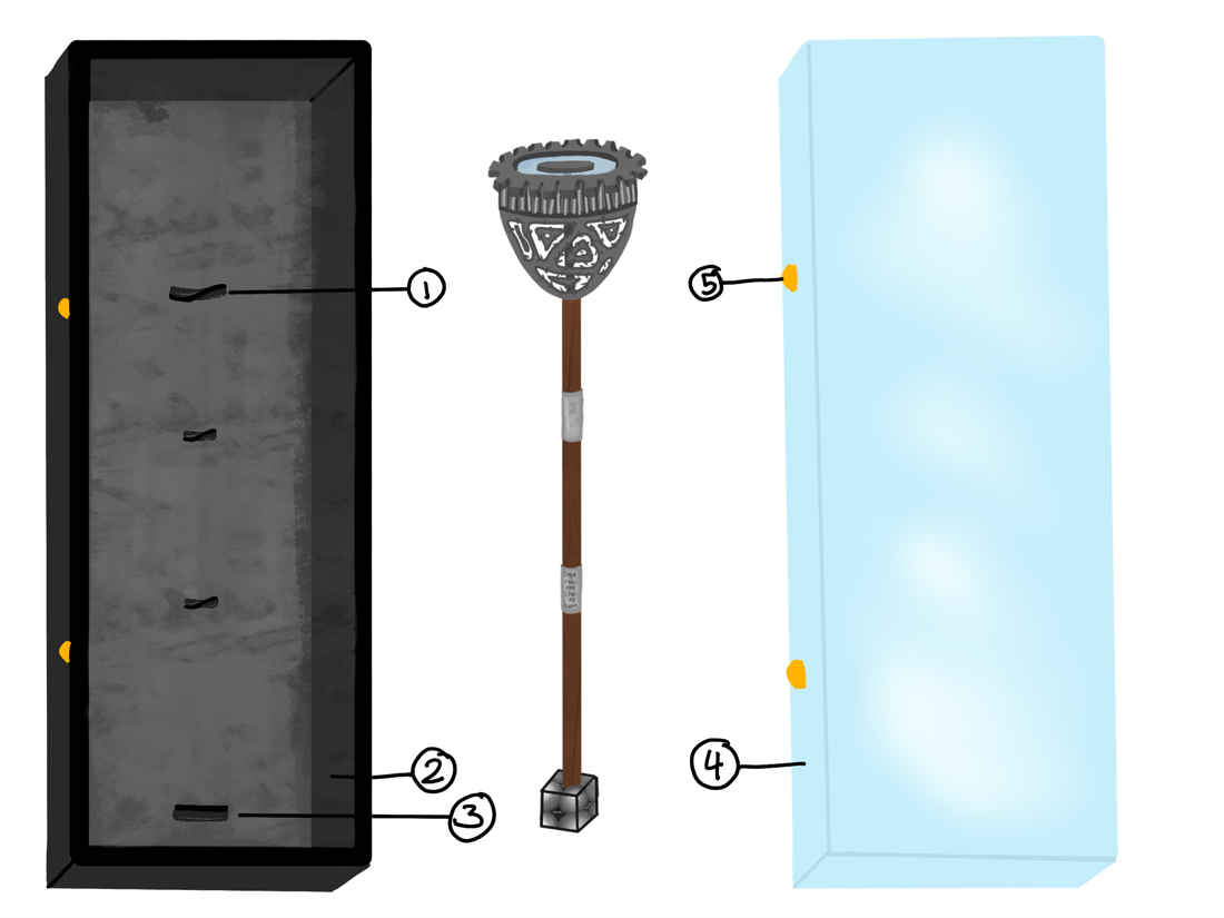
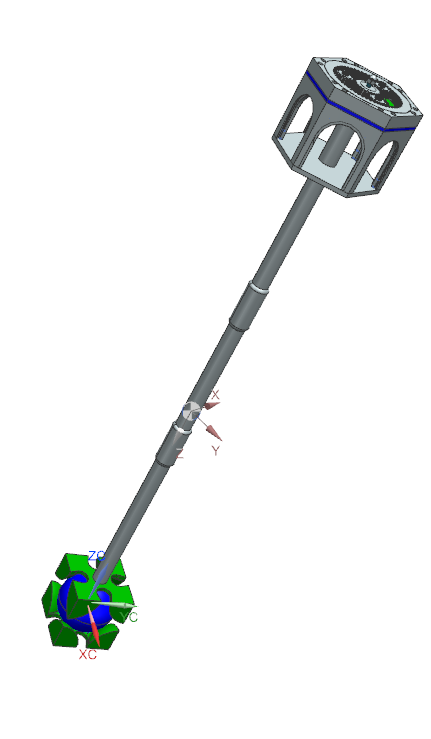
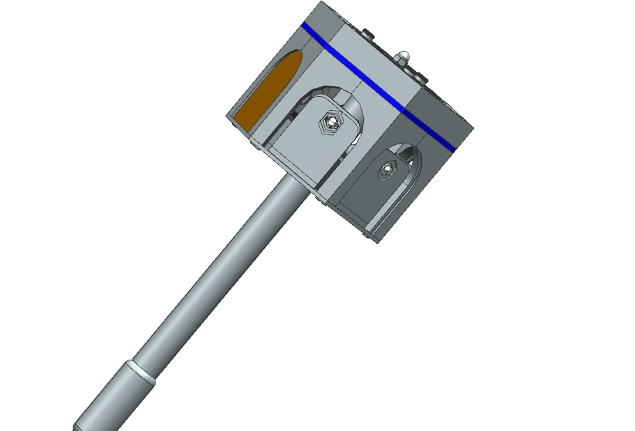
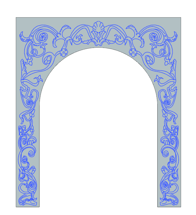
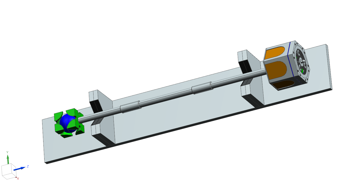
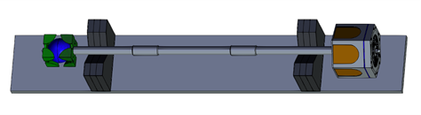
Since the initial concepts were based on the feedback of the Department’s staff, many of them share different versions of the same features. The final design takes inspiration from all the concepts from the Preliminary Design Report (PDR). The combination of these designs allowed each team member to have their own unique touch incorporated into the design as seen in Figure 1. The head of the mace has a planetary gear system at the top that adds a functionality aspect. There are six-faced archways that contain scrollwork to represent the artwork pictured in front of Gavett Hall’s front door. Within those arches are the six panels that contain the twelve different icons that highlight all facets of Mechanical Engineering studied here at Rochester (Figure 2). There are two clasps attached to the main shaft, both containing scrollwork to enhance the design. Both clasps also contain the names of the Mechanical Engineering Department Chairs and the Administrators, along with their years served. The staff of the mace is made of carbon fiber tubing which was picked as it is a very stiff material, and its slick black coloring adds to the general aesthetic of the mace. The base is in the shape of a BCC Structure to represent material science. There is a threaded aluminum rod that will be put through the mace to lock the components in place. This rod will serve to screw the ends together for additional support so that they do not fall apart.
In Zainab’s concept design (Table 4), the top includes a gear that acts as the crown of the mace. This gear is attached to a mechanism that allows it to rotate; as well as a lens that creates a light refraction display. Under the gear, there is a heat sink to incorporate another area of mechanical engineering. Beneath the heat sink is an aluminum sheet with a fluid flow pattern engraved on it. Parts of it are hollowed out to allow light to pass through and to show the inner mechanism and covered by plexiglass from the inside to avoid any outer materials from getting caught up. The wooden shaft is separated into three parts and held together through bands I and II, where band I will also act as a dial that will rotate the top gear. Band II will have the mechanical engineering department chairs’ names engraved. At the bottom of the mace, a steel BCC structure will balance the weight and it will have the team members’ names inscribed on it as well.
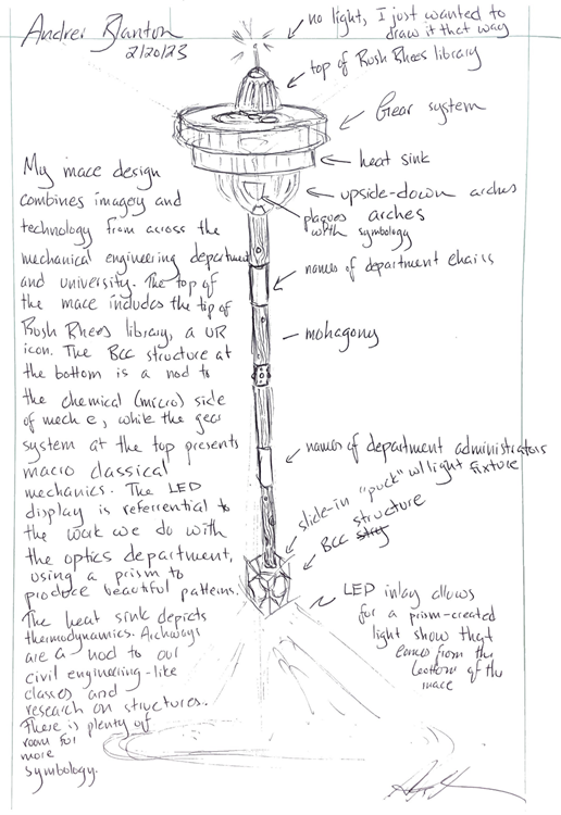
Andrei’s mace design (Table 5) combines imagery and technology from across the mechanical engineering department and University. The top of the mace includes the tip of Rush Rhees Library. The BCC structure at the bottom is a nod to the chemical (micro) side of Mechanical engineering, while the gear system at the top presents (macro) classical mechanics. The LED display represents the work the Department does with the Institute of Optics, using a prism to produce an appealing pattern. The heat sink depicts thermodynamics, and the archways for civil engineering.
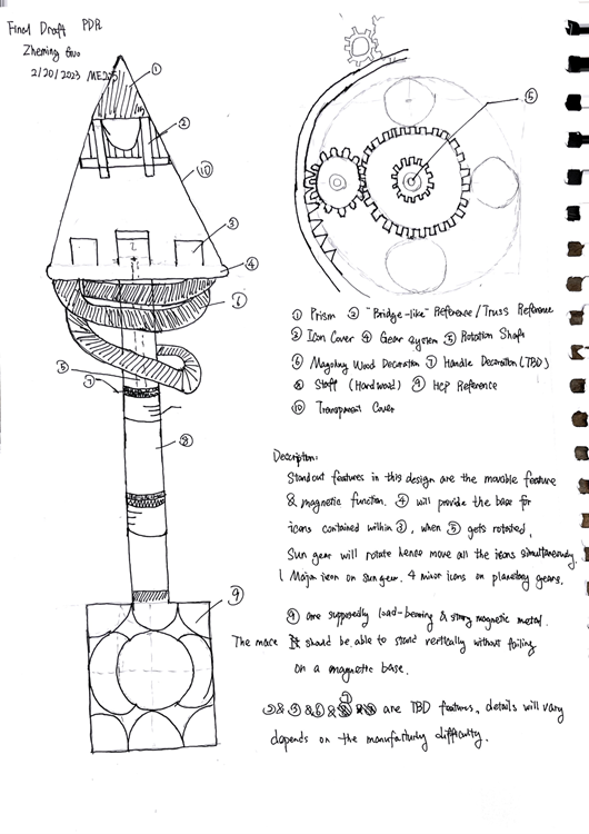
In Zheming’s design (Table 6), the standout features are the movable features and magnetic function. The gear system will provide the base for icons contained within the icon cover. When the shaft rotates, the gears rotate with it, and the icons will move simultaneously. The HCP base is load-bearing and magnetic; therefore, the mace should be able to stand vertically without failing magnetically. The rest of the features are to be determined based on the manufacturing difficulty.
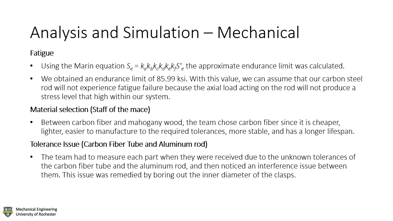
Fatigue failure is a common phenomenon in carbon steel materials, which occurs due to the repetitive application of stress below the yield strength of the material. Over time, this cyclic loading can cause microcracks to form and propagate through the material, eventually leading to failure. The severity and rate of fatigue failure depend on numerous factors, such as the stress amplitude, the number of cycles, the surface finish, and the environmental conditions. To prevent fatigue failure, designers must consider the expected load cycles and apply appropriate safety factors, while manufacturers can improve the fatigue resistance of carbon steel through material selection, surface treatment, and heat treatment. To analyze any fatigue failure issues, we used the Stress Limited Method. This method uses Eqn. (2), also known as the Marin equation, to approximate the endurance limit using factors such as surface condition, size, load, and temperature, along with other factors that may affect the integrity of the material. The endurance limit, also known as the fatigue limit, is the maximum stress level that a material can withstand indefinitely without experiencing fatigue failure. From our calculations, we obtained an endurance limit of 85.99 ksi. With this value, we can assume that our carbon steel rod will not experience fatigue failure because the axial load acting on the rod will not produce a stress level that high within our system.
Material selection is a critical aspect of mechanical design because it directly impacts the performance, cost, and durability of the final product. The right material must be chosen based on the specific requirements of the application, such as strength, stiffness, temperature resistance, corrosion resistance, and wear resistance. Selecting the wrong material can result in premature failure, increased maintenance costs, and safety risks. By selecting the right material, mechanical design can achieve optimal performance, longevity, and cost-effectiveness. In addition, the chosen material must also be suitable for the manufacturing process, which can affect the production cost and efficiency. Our first crucial material selection was tubing for the staff of the mace. The materials in question were carbon fiber and mahogany wood. Carbon fiber tubing is cheaper than mahogany wood tubing, which would allow our team to allocate funds toward more integral materials. Carbon fiber is also lighter than Mahogany which helped decrease the weight of the mace. Additionally, wood tubing is challenging to machine to the required tolerances, and the project team did not have the necessary woodworking experience to achieve the desired precision. Furthermore, wood tubing is prone to expansion and contraction, which could affect the clasp design and gear assembly. In contrast, carbon fiber tubing is more stable and will leave less room for error in the manufacturing process, making it an attractive option for projects that require durability and longevity. Overall, the cost-effectiveness, ease of machining, and superior performance makes carbon fiber tubing a better choice than wood tubing for this mechanical design. Another primary material selection is seen in the BCC structure where we used aluminum instead of steel. Now, our group is fully aware that a BCC is representative of steel however, due to manufacturing capability on campus with the HAAS machine and creating a mace that fits within our specifications for weight while still being balanced, there was not a feasible way to incorporate steel into the BCC of the designed structure.
The primary issue with our carbon tuber fitting is heavily related to tolerance issues. The carbon fiber tube was designed to be an inch thick and the aluminum rod which we ordered was also designed to be an inch with a small Tolerance to make sure that the tubing would fit over the fiber rod. The primary issue that we ran into was that the rod most suitable for our design, has an outer diameter of one inch with a tolerance of .012, whereas the aluminum rod that we ordered had an inner ID of 1 inch and there was no tolerance value listed on the part. As a result, we need to measure these exact dimensions once we receive the parts. When we received the parts, we measured the inner diameter of the aluminum tube and the outer diameter of the carbon fiber tube. Now when we received the parts the inner diameter of the aluminum rod was bigger than the outer of the carbon fiber tube by about 1 thousandth and this caused us to shave off three more thousandths to fit comfortably fit the rod on the carbon fiber tube. The issue that we did not account for even with the tolerancing was that there were slight bends in the rod that meant that the aluminum rod fits over some parts of the carbon fiber tube and not others and to protect the tube we then needed to take off about 3 more thousandths to make it fit.
The steel bearing, found at the center of the mace, could easily be considered one of the most paramount components within our design. This is the central part of the planetary gear system and allows for the top of the mace to rotate while the handle stays stationary within the hands of the one wielding it. The way the steel bearing works in this specific design is with the creation of a small lip or land created for the steel bearing to sit on. This allows the lip to sit on the inner race of the steel bearing in a stationary position. The idea is that we created this land big enough so that the inner race could comfortably sit on it but also big enough so that the lip would not interfere with the outer ring. If the land were too big then the bearing would create additional friction as the balls of the bearing spin around and thus slow it down. As a result, the dimensioning and execution of the middle clasp was pivotal. Now the lip in our design is only about a .02in thick ring with a depth of 2 thousandths of an inch. This allows the bearing which has an inner ledge of .19 to sit right on the lip and thus the lip barely interferes with the inner race; let alone the outer. Now the one potential issue that we may have, is that the lip is extremely small, however, it helps the bearing function when the mace is used held vertically to the ground. However, if the mace is tilted on an angle there will be slight movement in the gear system and the question then becomes, will the movement or stress applied to the internal claps or gear system, force enough movement to move the bearing off the lip and as a result cause the lip to interfere with the outer race of the balls that are rotating.
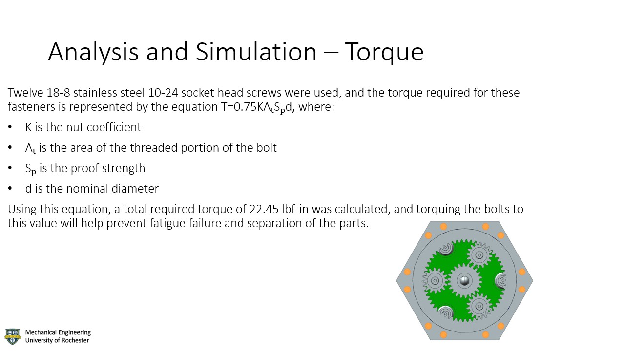
12 18-8 stainless steel 10-24 socket head screws were used to fasten the aluminum plate on the top of the head of the mace to the rest of the head. Since these fasteners are used in nonpermanent connections, the torque required for these fasteners is represented by Eqn. (1), where K is the nut coefficient, Aₜ is the area of the threaded portion of the bolt, Sₚ is the proof strength, and d is the nominal diameter. As K is an experimentally measured constant, an assumption of 0.3 will be made as this value is typical for steel fasteners without plating. Sₚ can be found to be 30,000 psi from the specification for 18-8 stainless steel, and d and Aₜ for a 10-24 fastener is 0.19” and 0.0175”, respectively. Substituting into Eqn. (1) yields a required torque of 22.45 lbf-in. This result allows the team to properly torque these bolts to prevent fatigue failure or separation.
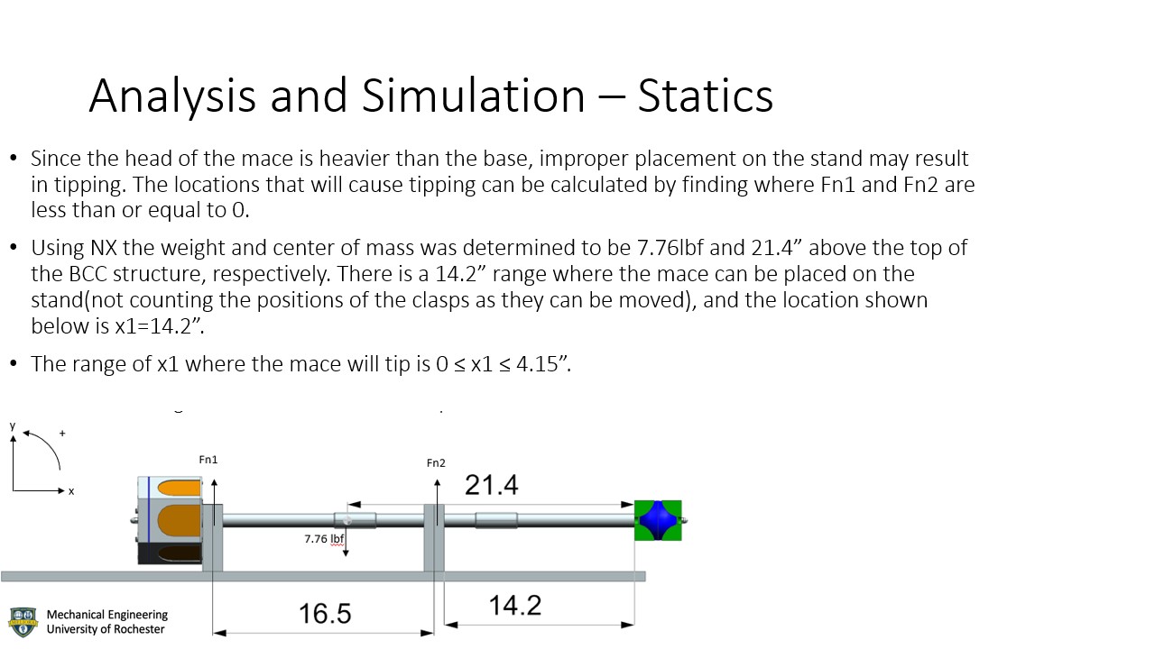
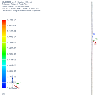
A simulation was made of the displacements of the carbon steel rod bearing the axial load of the head of the mace, which 4 Copyright © 20xx by ASME comes out to 4.84lbf and yields a maximum displacement of 1.46*10^-4 in(Figure 3).
Manufacturing methods are broken down into sections. Detailed description for components can be found in Table 1.
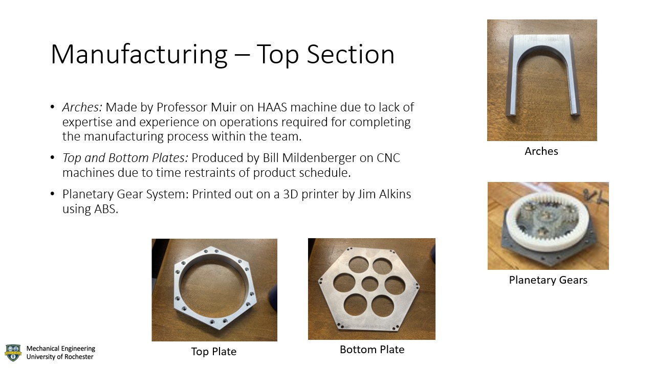
Arches: Made by Professor Muir on HAAS machine due to lack of expertise and experience on operations required for completing the manufacturing process within the team. Besides, the potential cost of damaging the machine is beyond mentioned team’s reach.
Central Plate: Made by technician Bill Mildenberger on CNC machines due to time restraints of product schedule.
Stand Plate: Same as Central Plate.
Rolling trajectory: Same as Stand Plate
Planetary Gear System: Printed out on 3D printer by Zheming Guo with ABS plastic.
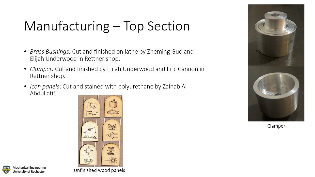
Brass Bushings: Cut and finished on lathe by Zheming Guo and Elijah Underwood in Rettner shop.
Clamper: Cut and finished by Zheming Guo and Eric Cannon in Rettner shop.
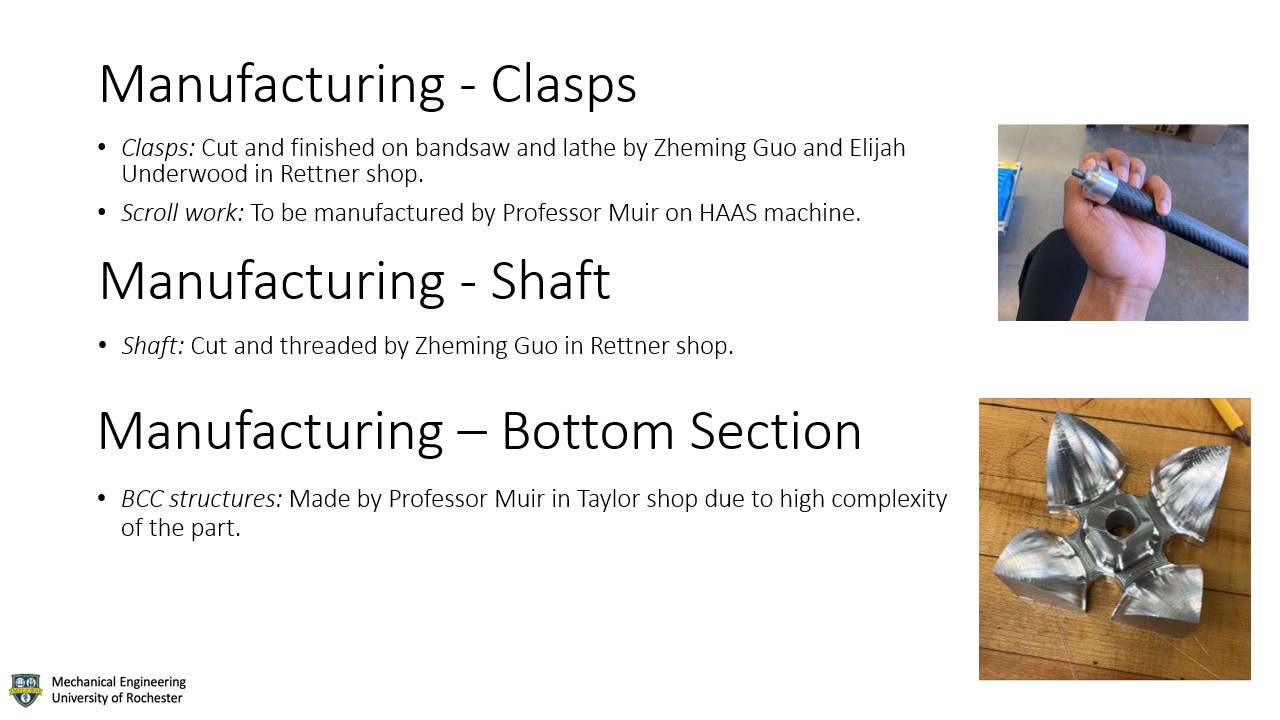
Clasps: Cut and finished on bandsaw and lathe by Zheming Guo in Rettner shop.
Scroll work: To be decorated by Professor Muir on HAAS machine.
Staff: Cut and threaded by Zheming Guo in Rettner shop.
BCC structure: Made by Professor Muir in Taylor shop due to high complexity of the part.
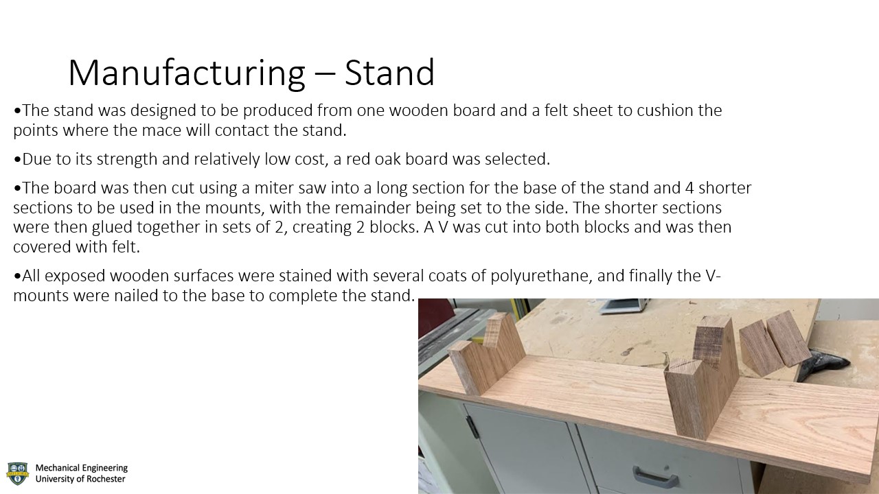
Stand: The stand was cut from a piece of red oak wood using a miter saw and a band saw, and a felt covering was attached to the mounts of the stand.
If the system were to be scaled to 1000 times in production, significant cost-cutting and time-saving measures could be implemented. Many of the parts ordered through McMaster have bulk order discounts, and there is likely some benefit from exploring other retailers for these materials. Several hand-machined parts could also be produced much cheaper and quicker with CNC, however, this would also come with the initial labor cost of developing the CNC programs.
The specifications of the final mace assembly will be tested through a scale for the weight and a measuring tape for both the length and radius. For the requirements of the mace being ornamental and using a wide variety of materials and manufacturing capabilities, this will be determined by the outcome of the final approval of the mace.
The ceremonial mace's design is not patentable by the Department as the design utilizes symbols such as the gear logo from Gavett Hall that are not necessarily exclusive to the Department, but it is possible the University could patent this device.
Since this device is symbolic in nature and only one unit will be produced, the scope of environmental implications from this projectis limited. One real concern is that if the carbon fiber staff is significantly damaged, it may emit toxic particles into the air that can be harmful to those in the immediate vicinity. For societal implications this device is intended to represent the Department, however, as technology changes very rapidly some symbols used may become outdated.
Due to time constraints and weight issues, a few planned components have been removed or significantly modified for the final design. In particular, the sphere we used for the BCC structure was aluminum, which does not exhibit the BCC crystal structure. This was because steel, the only metal with this structure that we can purchase a suitable sphere of within our price range, is far too heavy to be carried in the commencement ceremony. This could still be accomplished by hollowing out the sphere, but this would require an amount of planning and machining not compatible with this project's time limit. Since this device is intended to be used for many years, maintenance must be heavily considered, and all parts must be either repairable or replaceable in case of damage. Another large factor for future work around this device is future modifications. As the clasps contain the names of all the department chairs from the founding of the department to the present, it is a necessity that it be straightforward to add additional names. To address this, we allowed for a significant amount of extra length on the clasps for machining in additional names, and when the time comes to add the name of the next department chair this can be done so by etching them in with a CNC program.
Since this device is intended to be used for many years, maintenance must be heavily considered, and all parts must be either repairable or replaceable in case of damage. Another large factor for future work around this device is future modifications. As the clasps contain the names of all the department chairs from the founding of the department to the present, it is a necessity that it be straightforward to add additional names. To address this, we allowed for a significant amount of extra length on the clasps for machining in additional names, and when the time comes to add the name of the next department chair this can be done so by etching them in with a CNC program.
The team thanks Christopher Muir, Ed Herger, Bill Mildenberger, Chris Pratt, Jim Alkins, and Lyrica Yanaway for their support and guidance throughout various stages of the project.
Department of Mechanical Engineering - University of Rochester

|
Item Name |
Quantity |
$/Each |
Cost |
|
4-Axis CNC Hourly Cost |
25 (hr.) |
$100 |
$2500 |
|
3D Printing Hourly Cost |
8 (hr.) |
$50 |
$400 |
|
6 |
$7.46 |
$44.76 |
|
|
1 |
$14.62 |
$14.62 |
|
|
6 |
$2.87 |
$17.22 |
|
|
1 |
$11.10 |
$11.10 |
|
|
4 |
$42.91 |
$171.64 |
|
|
1 |
$10.73 |
$10.73 |
|
|
1 |
$62.19 |
$62.19 |
|
|
1 |
$97.49 |
$97.49 |
|
|
1 |
$18.35 |
$18.35 |
|
|
1 |
$26.87 |
$26.87 |
|
|
Permanently Lubricated Steel
Ball Bearing |
1 |
$19.35 |
$19.35 |
|
Black Anodizing Dye, 4 FL.
oz. |
1 |
$72.92 |
$72.92 |
|
Blue Anodizing Dye, 4 FL.
oz. |
1 |
$27.76 |
$27.76 |
|
Yellow Anodizing Dye, 4 FL.
oz. |
1 |
$27.76 |
$27.76 |
|
Orange Anodizing Dye, 4 FL.
oz. |
1 |
$27.76 |
$27.76 |
|
Shipping |
1 |
$72.25 |
$72.25 |
|
Total |
N/A |
N/A |
$3622.77 |
|
Component
Name |
Label |
Material |
|
Gears |
1 |
ABS |
|
Aluminum
Hex |
2 |
Aluminum |
|
Bearing |
3 |
Steel |
|
Steel Plate |
4 |
Steel |
|
Arches |
5 |
Aluminum |
|
Panels |
6 |
Wood |
|
Clamp |
7 |
Aluminum |
|
Clasps |
8 |
Aluminum |
|
Carbon Fiber
tube |
9 |
Carbon
Fiber |
|
Aluminum
Rod |
10 |
Aluminum |
|
BCC |
11 |
Aluminum |
|
Component Name |
Label |
Material |
|
Gear |
1 |
Aluminum |
|
Heat Sink |
2 |
Steel |
|
Lens |
3 |
Polycarbonate |
|
Fluid Flow |
4 |
Aluminum |
|
Opening |
5 |
Plexiglass |
|
Mechanism |
6 |
Steel |
|
Shaft |
7 |
Mahogany Wood |
|
Band I |
8 |
Aluminum |
|
Band II |
9 |
Aluminum |
|
BCC |
10 |
Steel |
|
Component Name |
Label |
Material |
|
Rush Rhees Library Feature |
1 |
Aluminum |
|
Gear Systems |
2 |
Steel |
|
Heat Sink |
3 |
Plastic |
|
Arch Features |
4 |
Plastic/Aluminum |
|
Staff Body |
5 |
Mahogany |
|
Engravings |
6 |
TBD |
|
LED-system |
7 |
Electronics Hardwares |
|
Prism |
8 |
Glass |
|
BCC Base |
9 |
Steel |
|
Fiber Bundle |
10 |
TBD |
|
Component Name |
Label |
Material |
|
Prism |
1 |
Glass |
|
Cantilever Bridge Feature |
2 |
Aluminum |
|
Icon Cover |
3 |
Glass |
|
Gear System |
4 |
Steel |
|
Rotation Shaft |
5 |
Alloy |
|
Mahogany Wood Decoration |
6 |
Wood |
|
Handle Decoration |
7 |
Vinyl Wrap |
|
Staff Body |
8 |
Softwood |
|
HCP Base |
9 |
Steel Alloy |
|
Top Cover |
10 |
ABS plastic |
|
Criteria |
University Mace |
|
Concept 2 |
Concept 3 |
Final Design |
|
Maintenance |
0 |
0 |
0 |
0 |
0 |
|
Aesthetic and Functionality |
0 |
1 |
1 |
1 |
1 |
|
Ease of Manufacturing |
0 |
0 |
0 |
0 |
0 |
|
Challenging background knowledge |
0 |
0 |
1 |
1 |
1 |
|
Total |
0 |
1 |
2 |
2 |
2 |
T=0.75KAₜSₚd (1)
Se = ka kb kc kd ke S'e (2)
The mace was designed to minimize the need for maintenace, however that is always impossible to eliminate completely and the device will eventually need some repairs or other maintenance. In particular the ABS gear system will need to be replaced if it is exposed to extended direct sunlight or another source of high temperatures, and also every 30 years regardless of use. The clasps are also intended to be reengraved with each new chair of the Department, and this can be done using the same CNC process that etched them originally.